
3. Types of RFID
The single acronym RFID is used to describe a variety of radio technologies, optimized for different types of applications. The key distinctions are in the radio frequency band employed for communications, the means by which the RFID tag is powered, and the conventions used for communicating between the tag and the reader.
Electromagnetic waves are cyclical phenomena: like waves on water, the electric field at each point in space oscillates back and forth as a wave passes by. The rate at which this oscillation occurs--the frequency of oscillation--is measured in Hertz, abbreviated Hz, commemorating the work of Heinrich Hertz, who confirmed Maxwell's prediction of the existence of electromagnetic waves. Radio frequencies are usually considered to extend from a few thousand Hz (kHz) to around 100 billion Hz (100 GHz). Electromagnetic waves move through air at the constant speed of light, so when the frequency increases the wavelength decreases. At 1 kHz the wavelength is about 300 kilometers (180 miles), the size of a small state or province. At 100 GHz, the wavelength is about 3 mm (0.1 inch). Changing the frequency changes the characteristics of the wave, and the way it interacts with the objects it encounters.
Most RFID applications use one of 4 rather widely-separated frequency bands (Figure 13). The band around 130 kHz is in the low-frequency or LF part of the radio spectrum. The wavelength is around 2000 meters (6000 feet), so all practical LF equipment is much smaller than a wavelength. LF radiation is largely unaffected by the presence of water (and thus by animal or human tissues), so LF tags can be placed on or even within animals or people. Livestock identification and pet tracking often employ LF technology; the system shown in Figure 6 uses an LF reader and LF ear tag. Since people don't block LF, it is also used for theft prevention. Because the reader antenna and tag are both much smaller than a wavelength, no propagating waves are launched into the world. Instead, the reader and tag antenna are inductively coupled: magnetic fields from the reader antenna induce voltages on the tag antenna, much like the primary and secondary windings of a transformer. Because the voltage induced at the tag is proportional to the frequency, LF tags usually use a coil with many windings to generate enough voltage for operation. Read range for inductively-coupled tags is roughly comparable to the size of the reader antenna. Thus compact readers can read tags from a few centimeters away, and a large antenna can have a read range of a meter or so. LF tags must send data at a rate low compared to the frequency of operation, so they are necessarily not very fast, and not suitable for moving large amounts of data rapidly from tag to reader, but LF readers are thus simple and inexpensive. LF tags are used in some access control systems and in key fob security systems for automobiles.

Figure 13: Common frequency bands used for RFID.
The band at 13.56 MHz, in the high-frequency or HF region, has long been used for industrial and medical applications and is available worldwide. The wavelength is around 20 meters (60 feet), still much larger than the readers and tags, so HF systems also use inductive coupling, and have read ranges similar to their LF compatriots. The higher frequency of operation allows for data rates of tens or even hundreds of kilobits per second, so HF tags can contain large amounts of data and still be read in a short time. The increased frequency also means that only 4-10 coil windings are needed to generate an acceptable voltage, so HF tag antennas can be readily created using the lithographic techniques used to make printed circuits. The magnetic fields used to couple HF tags and readers are rather insensitive to water and animal tissues, but the tag antennas themselves are designed for operation in air and don't function well if in direct contact with aqueous materials. HF technology is used in access cards, RFID-enabled credit cards and event tickets, and RFID-enabled passports. HF tags are also used for some item tagging applications. The tag depicted in Figure 11 is an HF tag.
RFID systems using the bands near 900 MHz or 2.4 GHz operate in the ultra-high-frequency (UHF) spectral region. Wavelengths in the UHF region vary from around 1 meter to 10 centimeters (3 feet to 4 inches), comparable in size to typical tags and readers, so UHF readers launch electromagnetic waves that propagate into the wider world. UHF tags and readers are thus usually radiatively coupled: a wave leaves the reader antenna and is received (and perhaps reflected) by the tag antenna. Read ranges of UHF devices can be much larger than an inductively-coupled technology allows; from a few meters to kilometers, depending on the power source used. However, because UHF readers send waves, interference between readers, and other radio devices in the same frequency band, is a problem. UHF tag data rates can be as high as hundreds of kilobits per second, so UHF tags can transfer large amounts of data quickly. UHF antenna structures are simpler to fabricate than LF or HF antennas, as only a single layer of metal is normally required. However, UHF waves are reflected by, and absorbed in, water and aqueous liquids, and tag antennas are strongly affected by proximity to aqueous liquids or metals. UHF systems are usually used for supply chain tracking at the carton or pallet level, asset tracking, navigation, and other applications where longer read range is a key advantage.
In the United States, unlicensed radio operation is allowed in the 902-928 MHz and 2.4-2.483 GHz industrial, scientific, and medical (ISM) bands, so these bands are commonly used for RFID applications. The 2.4 GHz band is also available for unlicensed use in most other jurisdictions, but the 902-928 MHz band is in the same frequency region widely employed for GSM cellular telephones. Most European countries allow RFID operation at 865-868 MHz. Regulatory provisions elsewhere in the world vary considerably (Figure 14). RFID systems operating around 900 MHz must be capable of functioning from around 860 to 960 MHz in order to be usable worldwide. See GS1 (PDF) wfor the latest UHF band regulations.

Figure 14: Summary of bands available for RFID use in the 860-960 MHz range.
Different operating frequencies require different tag antenna designs, as noted above. Figure 15 shows an example of typical antennas for each frequency range. LF antennas use multiple-turn coils (the tag shown, a glass encapsulated tag that can be implanted in a pet, uses a four-layer coil with around 400 turns wrapped around a ferrite rod that enhances magnetic response). HF antennas can use planar coils with a few turns to achieve ranges of tens of centimeters at credit-card size. UHF antennas are typically not coils but rather dipoles or monopoles, like the whip antenna on an automobile. Dipole antennas provide best performance at lengths around half of a wavelength (16 cm at 900 MHz, 6 cm at 2.4 GHz), but practical tag antennas are often shorter than that to allow the tags to be incorporated in standard-sized labels, tickets, or documents.

Figure 15: Examples of LF, HF, and UHF tags.
The means of providing power to an RFID tag, and of replying to an inquiry from a reader, are of more import in RFID than in most other radio applications. Most radios in our daily life are fixed devices powered from mains through a wall plug, or portable devices powered by an on-board battery. A cellular telephone is an example of the latter type of device. It contains a radio transmitter and receiver as well as signal processing and control circuits, and operates for a few tens of hours to a few days before requiring that the battery be recharged. Cellular telephones cost from US$50 to US$200 to manufacture (though the purchaser of such a phone may be subsidized by a service provider in exchange for a long-term contract). The cost and performance cited here work well for mobile telephony, but would be entirely inappropriate for many RFID applications. It is absurd to spend US$50 on a disposable tag that will uniquely identify one carton of items with a value of (say) US$100. Attaching tags to the thousands of components of a passenger airplane will not simplify maintenance if the tags need their batteries recharged every few days. RFID tags in many applications face requirements on cost and endurance that require more subtle approaches.
We can generally group the resulting technologies into three categories (Figure 16): passive, semi-passive, and active.
Figure 16: Approaches to providing power and tag-to-reader communications.
Passive tags do not use a battery or a plug; instead, all the power needed to operate the tag is derived from the radio signals sent by the reader. Furthermore, passive tags don't have a conventional radio transmitter and don't create their own signal. Instead, they vary the electrical load attached to the antenna in order to vary the signal reflected from the antenna, somewhat analogous to using a movable mirror to send a signal by reflecting the light of the sun towards a watcher. This technique is known as backscatter communications.
Passive tags are often extremely simple devices; the typical structure shown in Figure 17 consists only of a plastic substrate or inlay, a printed or etched metal antenna, and a single integrated circuit; as a consequence, passive tags can be much cheaper than other types of radio devices. A UHF passive tag including antenna can be sold for about US$0.10 in large volumes, 500 times cheaper than the cellphone described above, which is sold in similar volumes of hundreds of millions of units per year. A passive tag requires no maintenance, and has a long lifetime, limited by degradation of the tag materials rather than battery usage. It is reasonable to expect that passive tags will be readable for 10-20 years in many environments.

Figure 17: Typical UHF passive tag.
The tradeoff is that passive tags require hugely larger radio signals than conventional radios. The smallest signal a cell phone can detect is around one ten-trillionth of a watt (10-13 watts or -100 dBm). The sensitivity of a typical UHF passive RFID tag is about 10-100 microwatts: a passive tag requires around 100 million times more signal power to respond to a reader than a cell phone needs to talk to a base station. Roughly similar constraints apply for HF and LF operation. The consequence is that read ranges for passive tags range from centimeters to perhaps 20 meters (a few inches to 60 feet), instead of the tens of kilometers achievable with a cellphone. The read ranges quoted above for various frequency bands are those typical of passive operation.
Tags that use a battery to power the tag circuitry, but still employ backscattering or load modulation to communicate with the reader, are known as semi-passive or battery-assisted tags. Semi-passive tags require that the reader signal be large enough to decipher but don't need to extract power for their circuitry from it, so read range is no longer limited to a few meters. However, the use of backscatter radio means that when the distance from the reader to the tag is doubled, the signal received at the reader from the tag falls by a factor of 16: the signal at the tag falls by a factor of 4 (the inverse square of the distance), and the amount of the scattered signal that is received by the reader also falls by a factor of 4. In mathematical terms, the received signal is proportional to (1/r4), where r is the reader-tag distance. The read range of semi-passive tags is usually limited by this rapid decrease in the reader signal, but high-quality receivers can achieve read ranges on the order of 100 meters (300 feet) in unobstructed areas. Semi-passive approaches can also be used for LF and HF tags, though in many cases the applications where these technologies are employed may not require or tolerate long read ranges.
In addition to longer range, semi-passive tags provide much better reliability at short ranges. A passive tag 5 meters (15 feet) from a reader might not be read if the path from tag to reader is blocked by a person or other obstacle, even though significant amounts of electromagnetic radiation still reach the tag by diffraction around the obstacle or reflection from nearby surfaces. A semi-passive tag at similar ranges will often still be able to decipher and reply to the reader signal. Automobile tolling tags, like the one shown in Figure 4, are typically semi-passive devices for this reason. Reliable reads are achievable from cars traveling at high speed even in the presence of rain water and reflections from other vehicles.
The tradeoffs are that semi-passive tags are substantially more expensive than passive tags, and their applicability is limited by battery life. A semi-passive tag typically costs from US$2 to US$20. Designers take great pains to ensure that most of the circuitry is switched off except when the tag is being illuminated by a reader, but battery life is still generally limited to 3-5 years. In auto tolling applications, tolling authorities must replace transponders after a few years of service, incurring substantial administrative costs in addition to the replacement cost.
Active RFID tags are equipped with their own radio transmitter, like a cellphone or WiFi client. Active tags use conventional circuitry for transmission and reception, and read range and reliability are similar to the performance of other radios. Thus read ranges of hundreds of meters to kilometers (miles) are achievable, and tags can still be read despite substantial obstructions between the tag and reader. Active tags usually communicate at UHF frequencies (though not always in the 900 MHz range), as an inductively-coupled system does not achieve the same benefits in read range.
Along with improved read range and reliability go increased cost, size, and maintenance requirements. A comparison of a 2.4-GHz active tag and a 900-MHz passive tag, depicted at the same scale, is shown in Figure 18. It is readily apparent that the active tag, though the same height, is much thicker, and much more complex to fabricate than the simple passive tag. Some of the circuitry in an active tag can potentially be integrated into a smaller number of application-specific integrated circuits (ASIC's), but developing custom circuitry of this kind is expensive and requires a market for a large number of units to be profitable. Active tags cost US$20 to US$100 and are much too large to be used for tagging small, low-value assets.

Figure 18: Comparison of active and passive tags depicted at the same scale.
Active tags are often used for tracking expensive objects like shipping containers or trucks; such systems are often known as Real-Time Location Systems (RTLS). In these applications the tag may operate by sending a very brief identifying transmission, often known as a beacon, at infrequent intervals, thus conserving valuable battery power. The beacon may also contain timing information, allowing the tag to be located by using differences in the time of arrival of the tag signal at various readers whose locations are known. In order to further reduce battery drain, the tag may be set to beacon very infrequently, except when it detects the nearby presence of an exciter, a device that sends an LF signal. Since the range of the LF signal is very short, the tag will only become active when the exciter is very close to it. By mounting an exciter on a yard truck, trailer tags can be selectively activated only when the truck docks to the trailer--and is thus likely to move it--while remaining substantially inactive when they are stationary and their location can be presumed known (Figure 19). Fixed exciters may convey location information to the tag. Exciters can be used to mark specific physical locations, such as doorways, when active tags are used to track assets indoors.
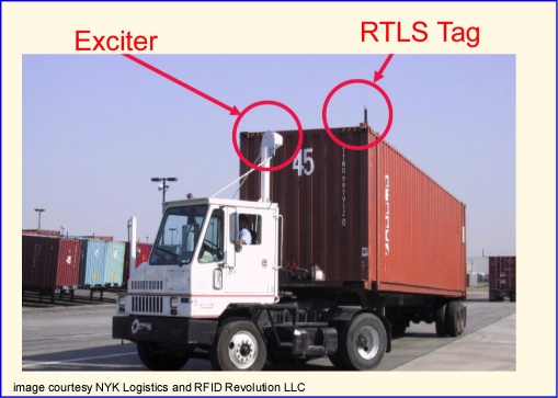
Figure 19: An exciter mounted on a cab causes a tag to beacon frequently when it is likely to be moved.
Every communications system must follow a set of conventions about how messages are sent, what the messages contain, and what the contents mean. These conventions are said to constitute the communications protocol. In an RFID context, the reader and tag must adhere to the same or compatible protocols, or no useful information will be transferred between them.
A radio communications protocol must typically specify such things as the coding of bits into a symbol, the frequency range of the carrier and modulation of the carrier wave to convert the symbol into a radio signal, the organization of the symbols into messages or packets, and the allocation of the medium when more than one station contends for the right to transmit (Figure 20). The last function is often referred to as medium access control or MAC. Protocols are generally organized in a hierarchical manner, so that (for example) the definition of the identifying information contained in a tag is independent of the specific means by which that information is moved from the tag to the reader.

Figure 20: Protocols specify the coding of bits into symbols, modulation of symbols onto the carrier, assembly of symbols into a message or packet, and allocation of the right to transmit packets.
Over the course of the long history of RFID applications, various protocols have been developed for specific applications; some of these protocols have then been codified into standards. Protocols have generally been optimized for specific applications, and often originate in the work of a specific vendor.
Different protocols can be compatible or incompatible. For example, under the moniker WiFi we find a suite of wireless networking protocols--802.11, 802.11b, 802.11g, and soon 802.11n--all of which are compatible. An 802.11g client can communicate, albeit at a reduced rate, with an 802.11b access point. This is possible because both parties are sophisticated radio devices equipped with complex adaptive software and firmware. A passive RFID tag must employ only the simplest logical capabilities to minimize power required to turn the device on; even an active tag must carefully manage the power consumed from the battery. RFID tags cannot generally provide the resources needed to adapt to multiple protocols; any versatility must be built into the reader.
In Table 1 we provide a few examples of RFID protocols, categorized by frequency band and tag power source. Tags that comply with one of these protocols are generally incompatible with readers that use another, even when the same frequency band is employed. For example, a reader sending ISO 18000-6A commands will only confuse an 18000-6B or 18000-6C tag. AAR S918 (the protocol used for railcar identification) is incomprehensible to a Title 21 auto toll tag. ISO 14443 passports can't understand ISO 15693 smart card readers.
Table 1: Some RFID communications protocols.
| frequency=> Power source | 124/134 kHz | 13.56 MHz | 860-960 MHz | 2.4 GHz |
|---|---|---|---|---|
| passive |
ISO 11784/5 ISO 14223 ISO 18000-2 |
ISO-14443 ISO 15693 ISO 18000-3 MIFARE |
ISO 18000-6A, B,C EPC Class 0, Class 1 AAR S918 |
ISO 18000-4 Intellitag Mu-chip |
| semi-passive |
California Title 21 EZ Pass AAR S918 |
ISO 18000-4 Alien BAP |
||
| active | Rubee |
ANSI 371.1 ISO 18000-4 |
Merely calling something "RFID" is thus not enough to tell much about it. In order to implement an RFID scheme for a specific application, it is thus necessary to consider what frequency bands can be used, what type of tag power source is appropriate, and what protocols are available to support those choices. The ability to find and track an active UHF tag across a wide area is very different from undertaking the same task for a passive HF tag, with different implications for personal privacy and data security. Lumping different types of technologies together without regard to their contrasting capabilities and limitations can be misleading.